Prairie River Bridge | Truss Assembly
Oct 21, 2022
Introduction
After the end posts were assembled, I assembled the chords and diagonals using the same techniques. I also assembled some of the truss panels and now it's time to finish the assembly of the three trusses by joining those panels with the remaining girders. I will also be building an assembly jig to hold the assembled trusses in the proper positions.
Truss Assembly
The prototype trusses would likely have been constructed in place using a cantilever approach or temporary structure of some sort. It is also possible that they were built on the ground and lifted into place on the piers using a crane. The only photograph of the original bridge is in the form of a postcard and no photos of its construction or later strengthening are known to exist.
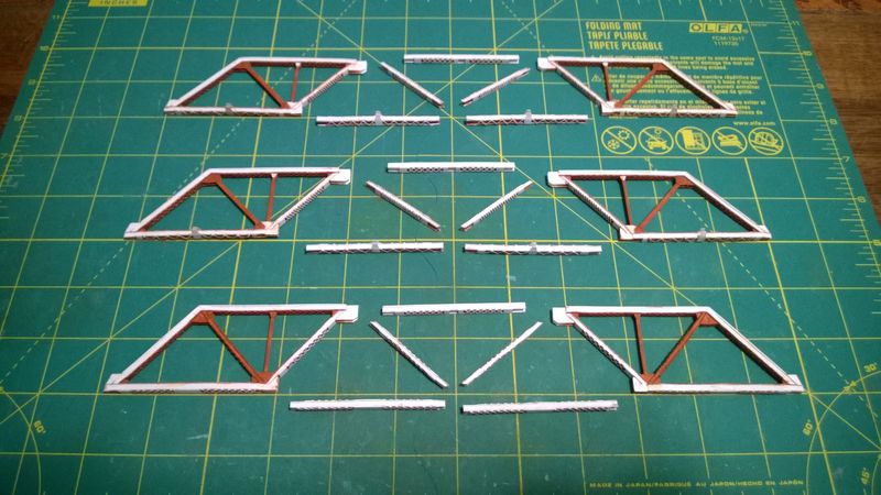
The end panels and remaining girders are laid out on the workbench as shown in Figure 1. One more set of gusset plates will be fabricated to connect the bottom chords and bottoms of the middle diagonals. Additional center verticals will be installed between the new center gussets and the center of the middle top chord, requiring two more connector plates. Short sections of "I" beam will also be installed between the upper gusset plates as can be seen on the prototype.
Archer Fine Transfers N Scale Resin Rivet decals are added to the remaining unfinished diagonal surfaces, followed with several thin layers of DecoArt Americana Burnt Sienna acrylic flat base coat. Rivet decals and base coat are also applied to the top surface of the second bottom chord and fastened to the lower gusset as shown in Figure 2
Two gusset plates are cut from 0.010" scrap styrene sheet from Evergreen Scale Models and attached to the end of the new lower chord. The third diagonal is installed between the upper and lower gusset plates. A small piece of "I" beam is fabricated from 0.010" styrene strip and installed between the upper gusset plates. Rivet decals and several thin layers of base coat are applied to the upper gusset plates and all surfaces of the new third diagonal.
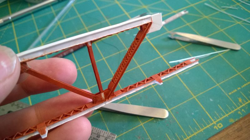
Two connector plates for the center vertical are cut from 0.010" scrap styrene sheet and attached to the opening in the bottom of the top center chord. Rivet decals and base coat are applied to the lower surface of the top center chord and attached to the upper gusset plates. The center vertical is fabricated from strips of 0.010" styrene and attached between the new connector plates on the top center chord and the lower center gussets as shown in Figure 3. The bottom and top chords should be parallel to each other.
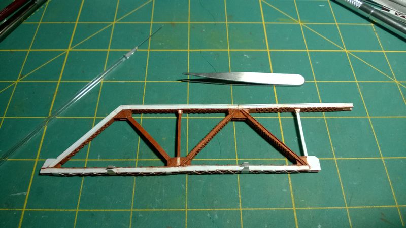
The top center chord is connected to the gusset plates on the second end panel. Several thin layers of base coat are applied to the center vertical. Rivet decals and base coat are applied to the laced surfaces of the final diagonal and the upper surface of the lower chord as shown on Figure 4. The remaining diagonal is attached between the upper and lower gusset plates.
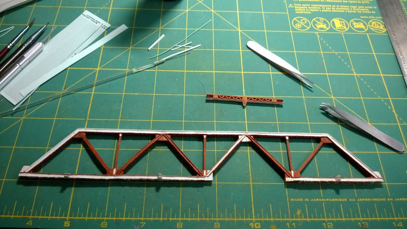
A small piece of "I" beam is fabricated from 0.010" styrene strip and installed between the upper gussets. Rivet decals and several thin layers of base coat are applied to the unfinished sides of the final diagonal and the upper gusset plates. The final bottom chord is attached to the remaining lower gusset plates and base coat are applied to touch up any interior areas as shown in Figure 5. The bottom and top chords should be parallel to each other.

Assembly Jig
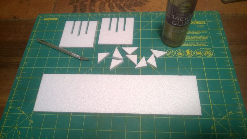
A rectangular base sheet and two square cradle supports are cut Woodland Scenics Subterrain foam sheet. Slots are cut in the cradle supports on scale 9-foot centers to hold the trusses when the jig is complete. The center slot is a scale three feet lower than the outer two slots to position the lower center truss as shown in Figure 6. Four right triangle gussets are cut from foam sheet to reinforce the cradle supports.
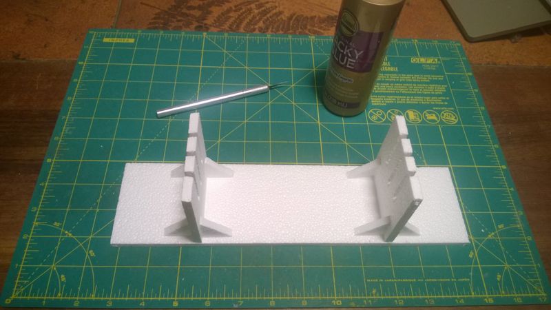
The two cradle supports are glued to the base sheet, about seven inches apart, using Aleen's Tacky Glue. Cradle supports should be perpendicular to the base sheet and parallel to each other. Gussets are added between the cradle supports and the base sheet to keep supports from swaying sideways as shown in Figure 7.
Conclusion
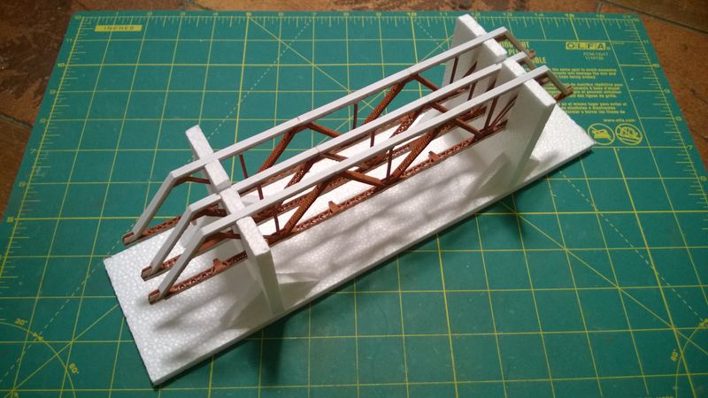
After assembling the first truss, I repeated the process for the other two trusses. Figure 8 shows the three assembled trusses sitting in the assembly jig that was just created. Now that they are assembled, I can finish detailing the side channels of the trusses before starting on the floor beams and stringers.
